Cable driven robots have been researched for decades and have seen some real usage [1]. They have the potential for reduced cost and increased performance, compared to a gearbox or direct-drive [2][3]. However there are a lot of limitations that make cable driven robotics challenging to design for.
One key limitation is with the winch. The winch can only store a finite
amount of cable, which means the output of the cable transmission can
only move a finite amount. With a gearbox or direct-drive, there is
generally no limit to the amount of rotation.
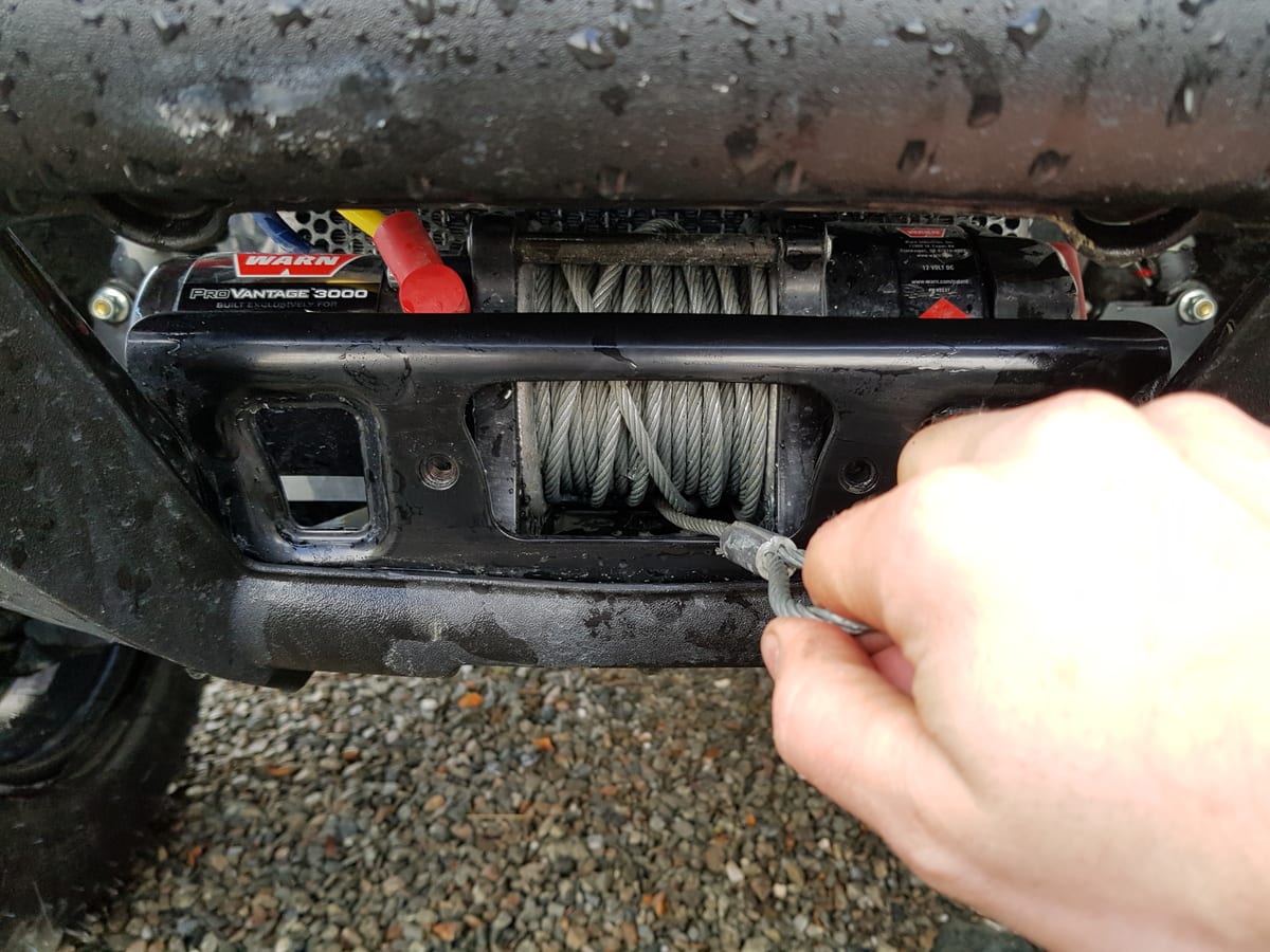 |
| A Winch for Off-Roading |
Winches designed for pulling cars out of ditches allow the cable to wrap over itself, greatly increasing its cable capacity. This is generally not done in robotic applications, because the cable wrapping over itself drastically changes the effective transmission ratio. If the cable always wraps over itself at the same location and time, then the transmission ratio change could be accounted for, but the process of winding a winch like this is fundamentally random. Consistent winding is particularly important when there is just one motor operating two separate winches. In robotics, this is required, because we need controlled motion in two directions, and cables can only pull.

The architecture shown above is typical for cable driven robots. Parallel cable driven robots are a notable exception [4].
This architecture can replace a gearbox for a serial robot where the joints have limited range of motion. One side of the winch unwinds while the other side winds up. Tension is maintained on the cable, allowing for zero backlash.
A key constraint of the method where two winches share one motor is that the cable must stay the same length to maintain tension. The figure below violates this constraint: the cable will not maintain the same length as the winch is wound and unwound.

As the cable winds up, the cable progresses across the winch (in z), and φ (phi) increases. This means that the hypotenuse of this triangle gets longer (Lmiddle). Lmiddle increases as the secant of φ (1/cos(φ)), so for small angles, the length change is small. For large angles, Lmiddle goes to infinity.
 |
| Secant of φ |
Many cable driven robots just use this setup with small angles and deal with the drawbacks. This works ok as long as there is enough compliance in the system to take up the length change. That compliance can come from the cable itself stretching, from another part of the system flexing, or from a spring element purposefully added somewhere in the system. Added compliance mostly solves the problem, but it reduces the bandwidth that can be controlled.
Another issue is that there is a large additional torque burden on the input motor, even if the system is very compliant. In addition to doing its intended task, the motor is now doing work to stretch the cable (or other spring). The compliance will also cause the actuator to snap back to the center when the motor is turned off.
Finally, compliance still only helps with relatively small angles, so the range of the actuator is limited.

The solution that is used for industrial cable systems, and many cable driven robots, is to add a cable guide (sometimes called a level winding mechanism) [5][6]. This cable guide moves along the winch as the cable spools up, keeping the angle relative to the winch at 90 degrees at all times. The cable then exits at another 90 degree angle, to be inline with the motion of the cable guide. In almost every application, this is the best solution. It allows for an arbitrarily large amount of cable to be spooled up on the winch, it lets you make the system very stiff, and the components that are added do not contribute to the accuracy or inaccuracy of the system (the cable guide leadscrew can be very sloppy).
Another solution is to put the entire motor and winch assembly on a linear bearing, and allow the winch grooves to act as the lead screw [7].
However, I was curious if there was another possible solution to this problem that doesn't introduce any new components. Particularly where there are cost and size constraints, adding an extra motion component for every axis is not desired. The concept I had is to adjust the radius of the winch very slightly to compensate for the length change.

The idea is that maybe there is some magical winch shape, where the radius changes as a function of theta (the rotation of the winch), that keeps the overall cable length constant as it winds and unwinds.
The basic formulation of that problem statement is:
`L_"total" = "constant"`
and therefore:
`d/(d\theta)L_"total" = 0`
So all I need to do is figure out a mathematical formulation for the total length of the cable, take its derivative, and figure out how to get it to equal zero. Check out part 2 here: https://blog.kyleb.me/2021/03/optimal-winch-design-part-2-nonlinear.html
References:
[1] Intuitive Surgical (Shameless plug of my teardown of their surgical tools: https://youtu.be/Xau6Qnt0wPE)
[2] ETH Zurich Capler Leg: https://arxiv.org/abs/1806.10632
[3] LIMS2-AMBIDEX: https://www.youtube.com/watch?v=DunpKVBC5Sc
[4] Room-scale parallel cable robot: https://www.youtube.com/watch?v=cJCsomGwdk0
[5] Level winder: https://www.youtube.com/watch?v=2_Mlk2jDUok
[6] Another level winder: https://www.youtube.com/watch?v=zvq0AtklQW8
[7] Clever winding solution: https://www.youtube.com/watch?v=pXqYp97VHjo