Tips for Mechanical Prototyping

Rules are meant to be broken. However they can give a solid starting point that guide your thinking. Here are some of the rules that I rely on to design projects.

Don't design your own bearings

When designing a machine, it is tempting to make a bearing or bushing that is just the right size or material for your application. In almost every case, you should not design your own bearing or bushing. Very experienced companies have spent billions of dollars figuring out how to make the most reliable and low friction bearings possible. Rely on that experience and manufacturing capability wherever possible. This applies to both linear and rotary bearings.

Another way to word this is "Use the best bearing you can for your application". Cost or size constraints might mean that a bronze bushing is the best bearing for a given design, but that's still better than a 3D print sliding on another 3D print.


Don't worry about keeping it simple

Often times simpler designs work better, are cheaper to make, and are easier to maintain. However coming up with simple designs is very difficult. A complex design that works is better than one hundred simple designs that don't work. Making things simpler should usually be a long-term design goal, but it is often counterproductive to consider it as a short-term goal.

A perfect example is this screw elevator design. It seems so simple that someone should've invented it 200 years ago. But they didn't, because coming up with a simple design that works is difficult. https://www.youtube.com/watch?v=-fu03F-Iah8

If you do want to make things simpler and follow the "KISS" approach, I think the best way to think about it is a quote from Einstein: "Everything should be made as simple as possible, but not simpler." It is too easy to compromise on requirements and features in search of some esoteric simplicity.


Move fast and break things (prototype)

From the outside, prototyping can seem like a waste of time and money. Prototypes are often complete failures that barely represent the final product. However this is the key feature of prototypes. They help you identify issues and failure modes that you didn't think about. Often times the failure mode that occurs in the prototype won't occur in the final product (due to material changes, manufacturing differences, etc), but it will get you thinking about failure modes you hadn't considered.

You don't know what you don't know, and prototypes help you find out some of what you don't know. The faster you put together a prototype that accomplishes some quanta of functionality, the faster you will identify issues. You very quickly run into an analytical limit just staring at CAD, so moving into the real world quickly is critical.

Prototyping is most useful when you approach it from a scientific perspective. In other words, have a specific question you want to answer, a hypothesis of what you think the answer will be, and a rough plan for how to get to an answer. This is how most corporate prototyping is structured, since it has a plan. People like plans. The problem is that you don't always have enough knowledge to know what question to ask. If you don't have a question, then you can't develop a plan. This is where exploratory prototyping comes in. Often times prototyping without a question and without a plan will be a waste of time. That's totally OK. The benefit from the times where you do learn something useful will offset the wasted time in the long run.

Shia Labeouf Just Do It GIF - Shia Labeouf Just Do It Do It - Discover &  Share GIFs


Prototyping is fundamentally wasteful and expensive

I have to remind myself of this fact for every personal project I work on. It's easy to optimize for cost too early in the process. At the same time, it's easy to spend way to much money on things that don't improve the project. Finding that balance on a budget is incredibly difficult and can be a big impediment to progress. The tip here is just to remember that the goal of making a project is not to save money. The goal is to make something.


Use your entire toolbox

It is easy to see a problem and immediately try to optimize it for a subset of your toolbox. What do I mean by toolbox? Your toolbox could mean what manufacturing technologies you choose, it could mean which suppliers you source from, or it could just mean what materials you try to make something out of.

There are myriad examples, but the most common lately is people trying to make everything 3D printed. Sure 3D printing is neat, but it isn't the best solution for most problems. Another example is trying to make everything out of carbon fiber. Carbon fiber is an incredible material, but it is also a massive pain. CF is not black aluminum. The design-side complexity of using CF usually makes it a poor solution, especially for version 1 of the project. 


Surf through McMaster

The fastest way to get to a solution is to look at how other people have solved similar problems. I find that the best source for solutions is McMaster. I have probably looked at every single product in the McMaster catalog, because all of them exist for a reason. Learning why a component exists and why people use it will give you insight into thousands of new solutions to possible problems. Misumi and other websites are also a great way to learn about new components, however McMaster is the best place to start since it is so well organized.
An example of what you can learn is in the linear bearings section:

There are 3,512 products in the linear bearings section. To a beginning mechanical engineer, this might seem absurd. If you've only ever seen linear bushings, then you would assume there would be a product for every diameter of bushing, so maybe a few hundred at the most. But, in fact, this section doesn't even include most of the linear bushings! Instead it includes a large variety of linear ball bearings. The purpose of a linear ball bearing over a linear bushing is not immediately obvious, and it becomes even less clear when you look at all the different types of linear ball bearings. I won't go into those specific purposes here, but it is an example of how you can learn about the breadth of solutions available at your fingertips in our globalized and commoditized world.


Read catalogs

Component manufacturers often have detailed catalogs that read like a concise and practical textbook. The exact part numbers found in these catalogs will not match other manufacturers, but usually the load ratings and capabilities of similarly sized components are transferable between brands. A guide rail made of stainless steel made by THK, IKO, NB, Hiwin, etc is going to perform very similarly regardless of brand. No-name low-cost components will likely have worse performance over time due to worse tolerances, but they are unlikely to be dramatically worse, so the catalog guidelines are still helpful.

Here are some catalogs I have found useful:

https://www.eichenberger.com/en/products/ball-screw

https://www.thk.com/catalog/?lang=en

https://www.hiwin.us/resources/catalogs/

https://www.ikont.com/brochures/ (Linear motion blue)


Use adhesives

Adhesives (glue and tape) are a great way to attach components together. The world is assembled using adhesives. Many people avoid using adhesives in prototyping for various reasons. Adhesives can be finicky to get right, but once you have a toolbox of options that you know how to use properly, using them can supercharge your prototyping speed. A small dab of glue can replace a dozen fasteners and improve the look and feel of an assembly. Since most adhesives will fail when you apply peel loading to them or when you heat them up, most assemblies can be taken apart after gluing.


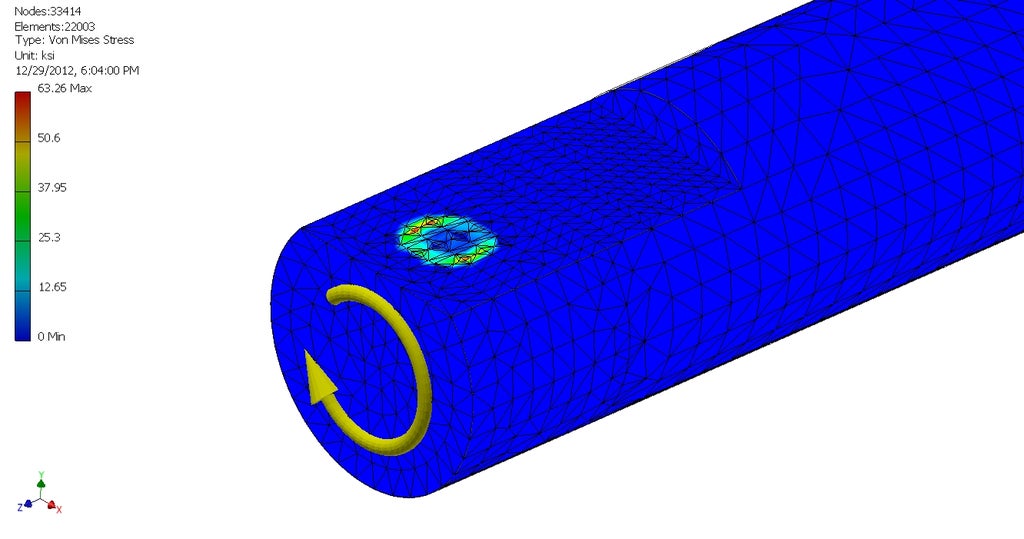
Don't rely on small set screws to transmit loads

Many off-the-shelf pulleys and gears use set screws to attach to the shaft and transmit loads. This works ok for very low torques, but often results in slippage that damages the shaft. Additionally, set screws are likely to loosen over time due to the oscillating loads usually applied to them.

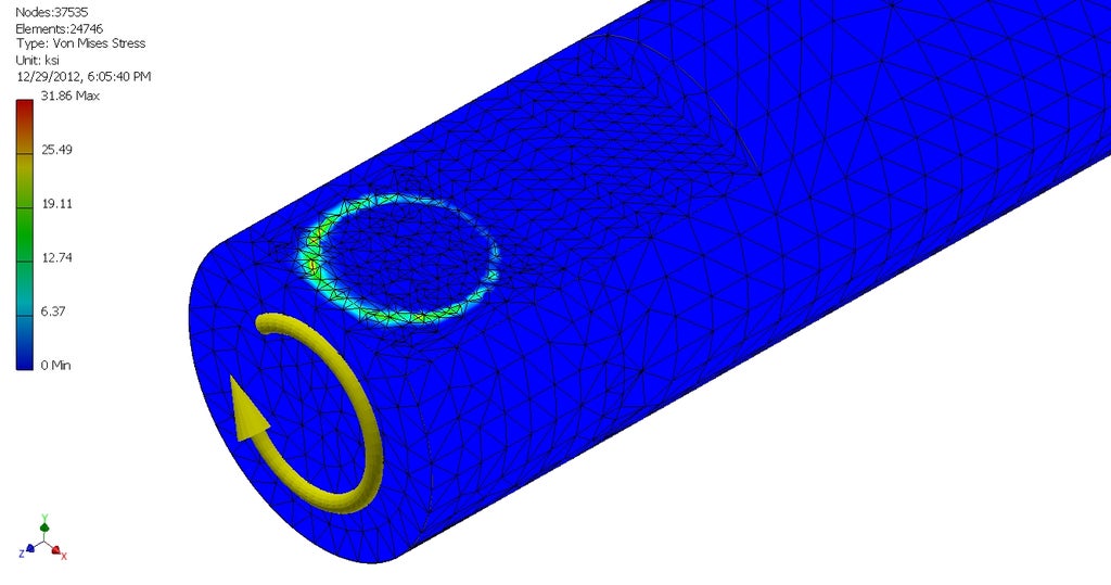
There are a few better options. The simplest is just to use a much larger set screw with a flat on the shaft (a D-shaft). This approximates a D-shaft and D-shaft bore. Most components with set screws can be drilled out and tapped to accept a larger screw.


Picture credit: Charles Guan https://www.instructables.com/How-to-Build-your-Everything-Really-Really-Fast/ 

There are many other good options for shaft connection. Keys, splines, actual D-shafts, pins, clamping collars (of all different designs), and finally glue. Gluing gears or other components to shafts is extremely common. It's a compact and low cost way to get a reliable shaft connection.


Optimal Winch Design, Part 2: Nonlinear Optimization

If you haven't read my intro post about this, check that out first: http://blog.kyleb.me/2021/02/optimal-winch-design-part-1-problem.html

Where we left off, I stated that the goal is:

    `d/(d\theta)L_"total" = 0`

Now all that's left is to find an expression for `L_"total"` and solve for `r(theta)`, right? 

Well the first part, yes, so let's tackle that first.


I split up the problem into 3 separate expressions for each side of the winch: `L_"winch"`, `L_"middle"`, and `L_"arc"`. This means that `L_"total"` is equal to:

`L_"winch1" + L_"middle1" + L_"arc1" + L_"constant" + L_"arc2" + L_"middle2" + L_"winch2"` 

`L_"winch"` Formulation

The easiest way that I found to formulate `L_"winch"` is to use parametric equations, where the parameter is theta (rotation of the winch). Here is the basic set of parametric equations describing the xyz location of a point on the winch helix:

`vec w = ((r(theta)cos(theta)), (r(theta)sin(theta)), (Ptheta))`

where:

`r(theta)` is a function describing a variable radius in terms of theta

`P` is the pitch of the helix.


The length of a parametric equation can be found with an arc integral:

`L_"winch" = int_0^(theta)||vec w'(theta)||  d\theta`

We will use this equation to verify the solution at the end, but our problem statement only requires the derivative of the winch length, so we can simplify the expression we need into the L2 norm of the derivative of the winch parametric equation vector:

`d/(d\theta)L_"winch" = ||vec w'(theta)||`

This form of the expression is critical, because it means we don't need to solve for the integral, which turns out to not have a closed-form solution for most forms of `r(theta)` (except maybe with elliptic integrals for some simpler forms of `r(theta)`).

I decided to use SymPy for the algebraic manipulation and analytical derivatives, to simplify the code and to allow for `r(theta)` to be changed easily.

`L_"middle"` Formulation

At least for me, formulating `L_"middle"` was a bit easier, since it's just a matter of doing some trigonometry. I'm sure there is a more elegant way of finding `L_"middle"`, but I decided to just draw some triangles:


Substituting in `Ptheta' for z, we get:

`L_"middle" = sqrt((Ptheta - r_"pulley")^2 + (H - r(theta))^2 + r_"pulley"^2)` 

where:

`H` is a constant for the height between the center of the winch axis and the center of the pulley.

`r_"pulley"` is a constant for the radius of the pulley.

Again, I then used SymPy to take the analytical derivative after substituting in an expression for `r(theta)`.

`L_"arc"` Formulation

In the previous figures, I showed another angle, `phi`. Given this angle, it is trivial to find the length of the arc on the pulley.

`phi = tan^-1(z/(H - r(theta)))`

Substituting in `Ptheta` for z, we get: 

`phi = tan^-1(Ptheta/(H - r(theta)))`

The length of the arc is just equal to `phi` times `r_"pulley"`:

`L_"arc = "r_"pulley"tan^-1(Ptheta/(H - r(theta)))`

 Solving for `r(theta)`

Ok so that's the first part out of the way. All the equations are defined. The issue is that now we have a pretty complex differential equation that we need to solve. Most differential equations simply don't have closed form solutions. There's no way to know for sure, but I'm fairly certain there is no closed form solution to this cable length equation. That means we need to use nonlinear optimization to find the best equation for `r(theta)`, to get `L_"total"` as close to zero as possible.

I started out by using SciPy's optimize.least_squares and optimize.minimize methods. My first implementation had some math errors, so I couldn't get the solvers to converge. In the process of troubleshooting, I switched to CasADi as my modelling and optimization tool. I'm sure one of SciPy's optimization algorithms would've worked fine, but this was a good opportunity for me to learn how to use CasADi anyways. CasADi is very powerful compared to SciPy, since it does automatic differentiation, which drastically improves solve times. For nonlinear programs, CasADi uses the IPOPT solver, which can solve large scale sparse problems, as well as smaller problems.

The optimization problem I've described is to optimize the derivative of the winch length, for all theta within a range. This is an infinitely dimensional optimization problem, since `r(theta)` could be anything. It could be a function with a billion parameters. So in order to actually solve the problem, we need to define `r(theta)` a little better.

This type of optimization problem, where the parameter that can be changed is a function, is most commonly seen in trajectory optimization problems. You can think of this winch problem as a controls problem, where there are no time dynamics, but the control input u is the instantaneous radius of the winch. Instead the differential equation defining the "dynamics" is relative to `theta`. So `theta` is analogous to time. The most common approach to trajectory optimization problems is to use splines to define the function, with some finite number of control points. This website has a lot of great resources about trajectory optimization: http://www.matthewpeterkelly.com/tutorials/trajectoryOptimization/

Spline based optimization is definitely the best option, but I decided to go with a simpler option to start, which is a single polynomial function. Since the solution is likely to be smooth and monotonic, a relatively low-order polynomial seemed like it would work. In the end, I found that a 1st order polynomial (i.e. a line) provided a remarkably good solution. The code allows you to specify any order polynomial. 2nd and 3rd order polynomials also worked well.

So what does our final winch look like?

Well it mostly looks like a cylinder. But it's actually subtly cone shaped:

 
It turns out that only a tiny bit of radius change is needed to keep constant length/tension. The set of parameters I chose are in millimeters, so the radius shown above is 7.7mm-8mm.
For those parameters, with a constant radius of 6.5mm, the total length of the cable would change by over 10mm. That's a huge amount that would probably cause the cable to break. With this linear radius shape, the cable length only changes by 0.017mm, which is about 20% the width of a human hair. I would call that a massive success!

This is what the cable length looks like versus theta, for a constant radius winch:

And the same plot for the optimized radius winch (note the drastically different vertical scale):


There is still some residual error, so I decided trying some other polynomials. This is the optimal solution with a 3rd order polynomial:

This time the radius change is much more dramatic.

There's another important parameter that isn't captured in the optimization problem, which is to reduce the amount of radius change over the winch. That parameter is important because as the radius changes, the effective force that a motor can put on the cable changes. That means the motor needs to be oversized to be able to handle all possible transmission ratios. This cubic radius solution is clearly worse than the linear solution, even though it is technically better at maintaining constant tension. Even with the linear radius model, we're well beyond manufacturing tolerances, so any improved performance is not necessary. But regardless, this does perform better at maintaining constant length, with a cable length change of only 0.003mm.


So the final question: Does this actually work in real life?

I don't know quite yet. I'm doing some testing with 3d printed models, which will hopefully be accurate enough to answer that. In the script, the verification portion that produces these length plots is somewhat separated from the optimization portion, but ultimately if my mathematical model is incorrect, the optimization and the verification will be incorrect. So the only real option is to try it on real hardware. Stay tuned for part 3.

Check out the code for this project on my Github: https://github.com/kylebme/winch-optimization

Optimal Winch Design, Part 1: Problem Statement

Cable driven robots have been researched for decades and have seen some real usage [1]. They have the potential for reduced cost and increased performance, compared to a gearbox or direct-drive [2][3]. However there are a lot of limitations that make cable driven robotics challenging to design for.

One key limitation is with the winch. The winch can only store a finite amount of cable, which means the output of the cable transmission can only move a finite amount. With a gearbox or direct-drive, there is generally no limit to the amount of rotation.

Image result for winch wound poorly
A Winch for Off-Roading

Winches designed for pulling cars out of ditches allow the cable to wrap over itself, greatly increasing its cable capacity. This is generally not done in robotic applications, because the cable wrapping over itself drastically changes the effective transmission ratio. If the cable always wraps over itself at the same location and time, then the transmission ratio change could be accounted for, but the process of winding a winch like this is fundamentally random. Consistent winding is particularly important when there is just one motor operating two separate winches. In robotics, this is required, because we need controlled motion in two directions, and cables can only pull.


The architecture shown above is typical for cable driven robots. Parallel cable driven robots are a notable exception [4].

This architecture can replace a gearbox for a serial robot where the joints have limited range of motion. One side of the winch unwinds while the other side winds up. Tension is maintained on the cable, allowing for zero backlash.

A key constraint of the method where two winches share one motor is that the cable must stay the same length to maintain tension. The figure below violates this constraint: the cable will not maintain the same length as the winch is wound and unwound.

As the cable winds up, the cable progresses across the winch (in z), and φ (phi) increases. This means that the hypotenuse of this triangle gets longer (Lmiddle). Lmiddle increases as the secant of φ (1/cos(φ)), so for small angles, the length change is small. For large angles, Lmiddle goes to infinity.

Secant of φ

Many cable driven robots just use this setup with small angles and deal with the drawbacks. This works ok as long as there is enough compliance in the system to take up the length change. That compliance can come from the cable itself stretching, from another part of the system flexing, or from a spring element purposefully added somewhere in the system. Added compliance mostly solves the problem, but it reduces the bandwidth that can be controlled.

Another issue is that there is a large additional torque burden on the input motor, even if the system is very compliant. In addition to doing its intended task, the motor is now doing work to stretch the cable (or other spring). The compliance will also cause the actuator to snap back to the center when the motor is turned off. 

Finally, compliance still only helps with relatively small angles, so the range of the actuator is limited.

The solution that is used for industrial cable systems, and many cable driven robots, is to add a cable guide (sometimes called a level winding mechanism) [5][6]. This cable guide moves along the winch as the cable spools up, keeping the angle relative to the winch at 90 degrees at all times. The cable then exits at another 90 degree angle, to be inline with the motion of the cable guide. In almost every application, this is the best solution. It allows for an arbitrarily large amount of cable to be spooled up on the winch, it lets you make the system very stiff, and the components that are added do not contribute to the accuracy or inaccuracy of the system (the cable guide leadscrew can be very sloppy).

Another solution is to put the entire motor and winch assembly on a linear bearing, and allow the winch grooves to act as the lead screw [7].

However, I was curious if there was another possible solution to this problem that doesn't introduce any new components. Particularly where there are cost and size constraints, adding an extra motion component for every axis is not desired. The concept I had is to adjust the radius of the winch very slightly to compensate for the length change.


The idea is that maybe there is some magical winch shape, where the radius changes as a function of theta (the rotation of the winch), that keeps the overall cable length constant as it winds and unwinds.

The basic formulation of that problem statement is:

`L_"total" = "constant"`

and therefore:

`d/(d\theta)L_"total" = 0`

So all I need to do is figure out a mathematical formulation for the total length of the cable, take its derivative, and figure out how to get it to equal zero. Check out part 2 here: https://blog.kyleb.me/2021/03/optimal-winch-design-part-2-nonlinear.html


References:

[1] Intuitive Surgical (Shameless plug of my teardown of their surgical tools: https://youtu.be/Xau6Qnt0wPE)

[2] ETH Zurich Capler Leg: https://arxiv.org/abs/1806.10632

[3] LIMS2-AMBIDEX: https://www.youtube.com/watch?v=DunpKVBC5Sc

[4] Room-scale parallel cable robot: https://www.youtube.com/watch?v=cJCsomGwdk0

[5] Level winder: https://www.youtube.com/watch?v=2_Mlk2jDUok

[6] Another level winder: https://www.youtube.com/watch?v=zvq0AtklQW8

[7] Clever winding solution: https://www.youtube.com/watch?v=pXqYp97VHjo


Surgical Robot Instrument Teardown and Analysis

 I recently created a detailed video showing how the Intuitive Surgical Robot instruments work, including a teardown where I fully disassembled the device.


The instruments shown in this video are from the DaVinci S/Si robotic surgery platforms. These surgery platforms, including the instruments shown, were developed in the mid 90's as a spin off of a university research project. The engineering in these instruments is pretty incredible, especially considering they pioneered robotic surgery with these devices.

Hoverboard Motor Teardown

I got some hoverboard motors in the mail! I decided to go with used ones to start, since they're just so darn cheap. The set of 2 hoverboard motors cost $30 (the price is now back to $40), with free shipping.

One of the motors didn't turn more than 90 degrees or so. So this one would be the first to come apart. They are very easy to take apart once you figure it out. Start with the 6 screws on the back. They have thread locker on them, so they might be tight. Next take the back cover off. It is not attached to the shaft, but it has a bearing and a seal on it, so it is hard to move it the first 1/2" or so. Once you wiggle it up that far using flat head screw drivers, you can pull it off by hand.


Now you can see the stator and the rotor magnets! The coils actually look quite good. Pretty clean windings.

The next step is to get the stator out. This can be a bit tricky, since the stator is a giant chunk of steel, surrounded by very strong magnets. I found that attaching it to my table vise with room underneath, then pulling very quickly upwards worked well. You want to go quickly because if you slowly apply pressure, it could get pulled down again. You want to get it out of the way of those magnets as soon as it loses grip.


This is the stator with the rotor already removed. You want the end of the flat part of the shaft to be touching the bottom of the vice, so that you can't pull the stator upwards. This works well because it also gives you plenty of room to grip the tire without risk of your fingers getting crunched.


And here's the culprit! This motor has a wave spring on both side of the shaft, presumably to apply a preload on the bearings. That's actually a nice feature, but this wave spring has broken into 3 pieces and is rubbing between the magnets and stator.


The magnets and stator are pretty scratched up from this, but it doesn't seem like it would affect the performance at all. I removed all the debris and put it back together and it seems to spin just fine.

On to the second motor:


This motor looks even nicer. It has some silastic holding the wires in place and darker insulation on the wires, which I assume means it's thicker.


The magnets still have their coating on them too, which is good. This motor also feels heavier. It looks like the stator and the rotor are both significantly heavier, but it turns out this isn't the case.

Motor 1 (Yuanxing branding on the tire):
 

My scale doesn't go quite high enough for the full motor, so I'll just add up these masses for the final mass. The total mass of motor 1 is 2.97kg

Motor 2 (Risingsun branding on the tire):


The total mass of motor 2 is 3.01kg. So they are almost the exact same mass. Despite looking heavier and having a stronger magnetic pull, the stator in motor 2 is actually lighter. The rotor in motor 2 is definitely heavier, though, and you can feel it. The outside surface seems to be thicker aluminum.

Having a low rotational inertia is pretty important for robotics applications, and these motors currently have a giant ring of rubber around the outside of them. Inertia scales as mr^2, so having a lot of mass around the outside is especially bad. Let's try to take the tire off!


That was easy! Here's a video of the process:


First I use a hacksaw to cut as far as possible without cutting the aluminum rim. Then use a sharp utility knife to cut as much as possible away. Then use a flat head screwdriver to pull the tire up and use the knife to cut it the rest of the way. The tire shouldn't be glued or attached in any way, so once there's a cut going all the way through, it should just detach.

The tire does seem to weigh quite a lot. Here are the two tires from the two motors:


So somewhere around 415g. That reduces the mass of the rotor from about 1.4kg to less than 1kg!

I think these will make excellent motors. Stay tuned for some testing with the ODrive.

Hoverbots

There are a large number of parts that make robots expensive. Luckily all of them are getting cheaper. This started with the processors getting better and cheaper because of the popularity of smartphones. It has moved to linear motion components and aluminum extrusions due to the popularity of 3d printers. Most recently it has moved to the drive electronics, like with the ODrive project, which is an open source brushless servo motor controller.


A key part that has always been expensive is the actuators that move the robot. These could be pneumatics, hydraulics, brushed motors, or brushless motors. In all of these cases, moving quickly, precisely, or with large forces meant expensive actuators. The best option has been brushed DC motors, but these are not very power dense, due to the mass of the brushes, the inefficiency of the commutation, and the limit of power that can flow through brushes.

https://www.rcjuice.com/media/wysiwyg/Brushed_Motor.jpg
Good motors got a lot cheaper when hobby rc brushless motors got more popular. You can buy a relatively high quality motor that can output multiple kilowatts of power for less than $50. Unfortunately most of these motors just aren't meant for robotics applications. They are usually wound for high speed rotation to power a propeller. They are actually ideal if you use a big gearbox (10:1 or more), but gearboxes are exceedingly expensive; many times the cost of the motor itself. There are "affordable" motors available with the specs needed, but they are still pretty expensive since they are for a niche market (at least $300).

Now imagine you are a 13 year old kid who loves Vine and [insert other Gen Z stereotypes here]. You don't care about all this dumb motor stuff. You just want a cheap hoverboard. So China obliged.

Image result for viner hoverboard

Hoverboards are super cheap. A pretty standard price is $150. So for $150 you get a frame, a gyro stabilizer board, a Lithium Polymer battery, 2 brushless motor controllers, and 2 super high torque brushless motors.

We don't really care about all the other stuff, but the part that's interesting is the motors. It turns out that these motors can output 20-30Nm of peak torque. That is an insanely large number. But what's more is the price. You can pick up a brand new motor on Amazon for $40. And if you order direct from China you can get it for less than $20! These motors are practically the same price as the raw materials going into them. Used motors go for around $15 on ebay.

What makes them so cheap? They certainly aren't high quality devices. You wouldn't want these motors anywhere safety critical. The main thing that makes them cheap is the insane quantity that they're manufactured in. Here's a picture from a seller on Alibaba who says they can supply 30,000 units per week:

http://sc01.alicdn.com/kf/HTB1kX9aOVXXXXcQXFXX760XFXXXY/227330825/HTB1kX9aOVXXXXcQXFXX760XFXXXY.png

This new source of high torque, low cost motors got me thinking about what I could do with one. So I came up with a few fun ideas.

The first idea is something like Boston Dynamics Spot, or the MIT Cheetah.

5'9" angle dude for scale 
This is using a belt drive system. This is similar to the newest version of the MIT Cheetah, which uses chain for the knee joint.

5'9" angle dude for scale 
This is using a direct drive, delta type system. This version is very similar to the MIT mini Cheetah robot, or to the GOAT leg.

Both of these robots could be built for around $1000 including everything. That is dirt cheap compared to the hundreds of thousands of dollars that go into a Boston Dynamics or MIT robot.

Here's the approximate cost breakdown:
Hoverboard Motors: 8x $20: $160
Encoders: 8x $20: $160
ODrive Motor controllers: 4x $150: $600
Mechanical Parts: $150-$300
"Brains": $50-$500 (Beaglebone to Nvidia Jetson)

So the cost ends up being somewhere around $1k-$1.5k.

Another idea I had was a delta robot. Usually these robots have high speed motors with large gear ratios. This is probably technically better, but we're looking for cheaper, and gearboxes are expensive. So instead I think this would work great with no gearbox and 3 hoverboard motors.

I haven't put together a CAD sketch of what it would look like yet, but it would be basically exactly the same as any angular delta. Most 3d printers use a linear delta configuration, so check out industrial delta robots if you want to see what those look like:

Image result for delta robot

Oskar from ODrive Robotics is working on a large robot arm using these motors, so that will be awesome too.

As I come up with more neat ideas for cheap robotics that can use these motors, I will post them here.

New Blog

I'm starting this blog as a new way to document my projects. In the past, I haven't kept a good log of projects, or the logs were in different locations. A lot of my projects ended up having their own documentation, but it just didn't work well.

For now, most of my projects are going to be robotics related. Once I finished a project, or get to a significant milestone in it, I will add it to my project portfolio. Check it out at kyleb.me/projects

The projects documented on this blog are done on my personal time, unrelated to my full time job.