Hoverboard Motor Teardown

I got some hoverboard motors in the mail! I decided to go with used ones to start, since they're just so darn cheap. The set of 2 hoverboard motors cost $30 (the price is now back to $40), with free shipping.

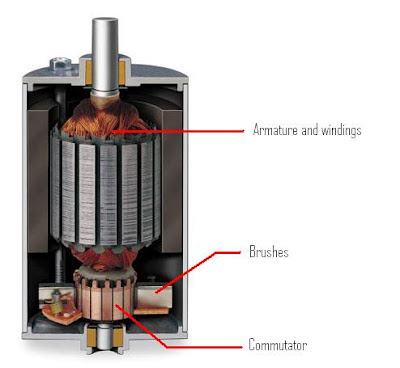
One of the motors didn't turn more than 90 degrees or so. So this one would be the first to come apart. They are very easy to take apart once you figure it out. Start with the 6 screws on the back. They have thread locker on them, so they might be tight. Next take the back cover off. It is not attached to the shaft, but it has a bearing and a seal on it, so it is hard to move it the first 1/2" or so. Once you wiggle it up that far using flat head screw drivers, you can pull it off by hand.


Now you can see the stator and the rotor magnets! The coils actually look quite good. Pretty clean windings.

The next step is to get the stator out. This can be a bit tricky, since the stator is a giant chunk of steel, surrounded by very strong magnets. I found that attaching it to my table vise with room underneath, then pulling very quickly upwards worked well. You want to go quickly because if you slowly apply pressure, it could get pulled down again. You want to get it out of the way of those magnets as soon as it loses grip.


This is the stator with the rotor already removed. You want the end of the flat part of the shaft to be touching the bottom of the vice, so that you can't pull the stator upwards. This works well because it also gives you plenty of room to grip the tire without risk of your fingers getting crunched.


And here's the culprit! This motor has a wave spring on both side of the shaft, presumably to apply a preload on the bearings. That's actually a nice feature, but this wave spring has broken into 3 pieces and is rubbing between the magnets and stator.


The magnets and stator are pretty scratched up from this, but it doesn't seem like it would affect the performance at all. I removed all the debris and put it back together and it seems to spin just fine.

On to the second motor:


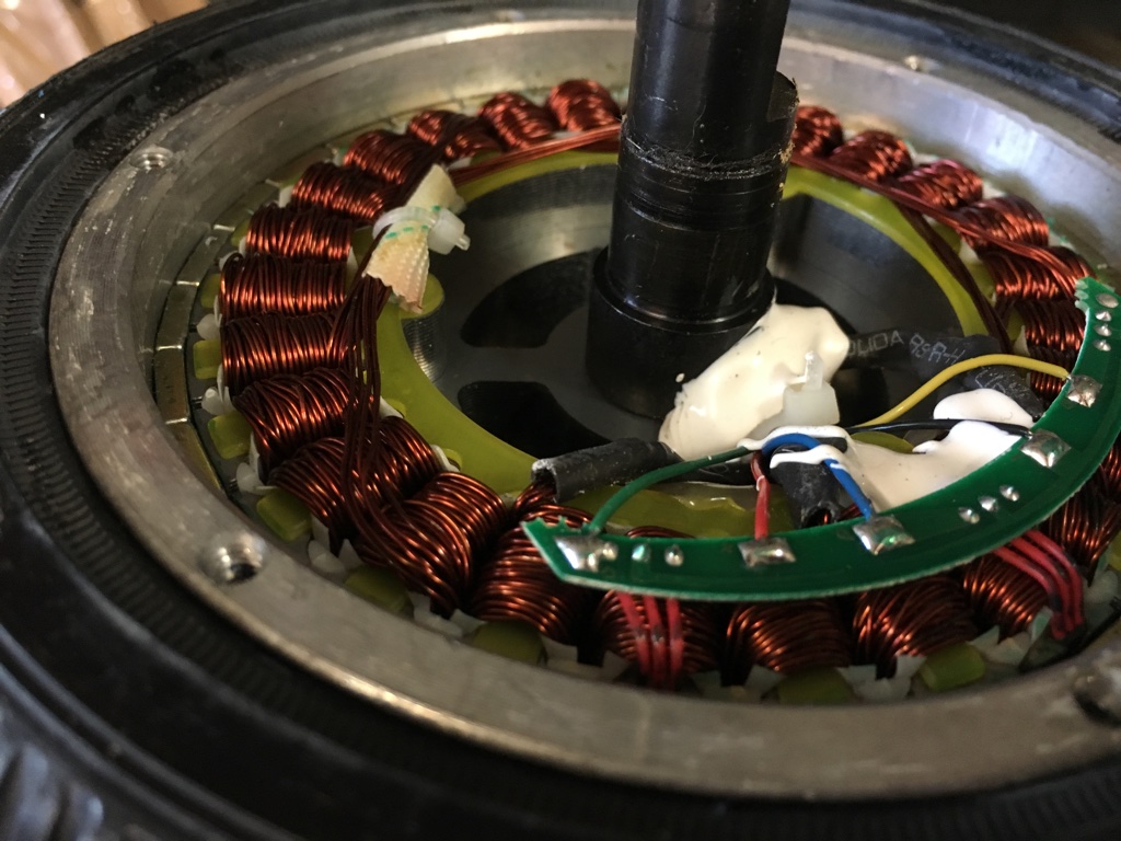
This motor looks even nicer. It has some silastic holding the wires in place and darker insulation on the wires, which I assume means it's thicker.


The magnets still have their coating on them too, which is good. This motor also feels heavier. It looks like the stator and the rotor are both significantly heavier, but it turns out this isn't the case.

Motor 1 (Yuanxing branding on the tire):
 

My scale doesn't go quite high enough for the full motor, so I'll just add up these masses for the final mass. The total mass of motor 1 is 2.97kg

Motor 2 (Risingsun branding on the tire):


The total mass of motor 2 is 3.01kg. So they are almost the exact same mass. Despite looking heavier and having a stronger magnetic pull, the stator in motor 2 is actually lighter. The rotor in motor 2 is definitely heavier, though, and you can feel it. The outside surface seems to be thicker aluminum.

Having a low rotational inertia is pretty important for robotics applications, and these motors currently have a giant ring of rubber around the outside of them. Inertia scales as mr^2, so having a lot of mass around the outside is especially bad. Let's try to take the tire off!


That was easy! Here's a video of the process:


First I use a hacksaw to cut as far as possible without cutting the aluminum rim. Then use a sharp utility knife to cut as much as possible away. Then use a flat head screwdriver to pull the tire up and use the knife to cut it the rest of the way. The tire shouldn't be glued or attached in any way, so once there's a cut going all the way through, it should just detach.

The tire does seem to weigh quite a lot. Here are the two tires from the two motors:


So somewhere around 415g. That reduces the mass of the rotor from about 1.4kg to less than 1kg!

I think these will make excellent motors. Stay tuned for some testing with the ODrive.

Hoverbots

There are a large number of parts that make robots expensive. Luckily all of them are getting cheaper. This started with the processors getting better and cheaper because of the popularity of smartphones. It has moved to linear motion components and aluminum extrusions due to the popularity of 3d printers. Most recently it has moved to the drive electronics, like with the ODrive project, which is an open source brushless servo motor controller.


A key part that has always been expensive is the actuators that move the robot. These could be pneumatics, hydraulics, brushed motors, or brushless motors. In all of these cases, moving quickly, precisely, or with large forces meant expensive actuators. The best option has been brushed DC motors, but these are not very power dense, due to the mass of the brushes, the inefficiency of the commutation, and the limit of power that can flow through brushes.

https://www.rcjuice.com/media/wysiwyg/Brushed_Motor.jpg
Good motors got a lot cheaper when hobby rc brushless motors got more popular. You can buy a relatively high quality motor that can output multiple kilowatts of power for less than $50. Unfortunately most of these motors just aren't meant for robotics applications. They are usually wound for high speed rotation to power a propeller. They are actually ideal if you use a big gearbox (10:1 or more), but gearboxes are exceedingly expensive; many times the cost of the motor itself. There are "affordable" motors available with the specs needed, but they are still pretty expensive since they are for a niche market (at least $300).

Now imagine you are a 13 year old kid who loves Vine and [insert other Gen Z stereotypes here]. You don't care about all this dumb motor stuff. You just want a cheap hoverboard. So China obliged.

Image result for viner hoverboard

Hoverboards are super cheap. A pretty standard price is $150. So for $150 you get a frame, a gyro stabilizer board, a Lithium Polymer battery, 2 brushless motor controllers, and 2 super high torque brushless motors.

We don't really care about all the other stuff, but the part that's interesting is the motors. It turns out that these motors can output 20-30Nm of peak torque. That is an insanely large number. But what's more is the price. You can pick up a brand new motor on Amazon for $40. And if you order direct from China you can get it for less than $20! These motors are practically the same price as the raw materials going into them. Used motors go for around $15 on ebay.

What makes them so cheap? They certainly aren't high quality devices. You wouldn't want these motors anywhere safety critical. The main thing that makes them cheap is the insane quantity that they're manufactured in. Here's a picture from a seller on Alibaba who says they can supply 30,000 units per week:

http://sc01.alicdn.com/kf/HTB1kX9aOVXXXXcQXFXX760XFXXXY/227330825/HTB1kX9aOVXXXXcQXFXX760XFXXXY.png

This new source of high torque, low cost motors got me thinking about what I could do with one. So I came up with a few fun ideas.

The first idea is something like Boston Dynamics Spot, or the MIT Cheetah.

5'9" angle dude for scale 
This is using a belt drive system. This is similar to the newest version of the MIT Cheetah, which uses chain for the knee joint.

5'9" angle dude for scale 
This is using a direct drive, delta type system. This version is very similar to the MIT mini Cheetah robot, or to the GOAT leg.

Both of these robots could be built for around $1000 including everything. That is dirt cheap compared to the hundreds of thousands of dollars that go into a Boston Dynamics or MIT robot.

Here's the approximate cost breakdown:
Hoverboard Motors: 8x $20: $160
Encoders: 8x $20: $160
ODrive Motor controllers: 4x $150: $600
Mechanical Parts: $150-$300
"Brains": $50-$500 (Beaglebone to Nvidia Jetson)

So the cost ends up being somewhere around $1k-$1.5k.

Another idea I had was a delta robot. Usually these robots have high speed motors with large gear ratios. This is probably technically better, but we're looking for cheaper, and gearboxes are expensive. So instead I think this would work great with no gearbox and 3 hoverboard motors.

I haven't put together a CAD sketch of what it would look like yet, but it would be basically exactly the same as any angular delta. Most 3d printers use a linear delta configuration, so check out industrial delta robots if you want to see what those look like:

Image result for delta robot

Oskar from ODrive Robotics is working on a large robot arm using these motors, so that will be awesome too.

As I come up with more neat ideas for cheap robotics that can use these motors, I will post them here.

New Blog

I'm starting this blog as a new way to document my projects. In the past, I haven't kept a good log of projects, or the logs were in different locations. A lot of my projects ended up having their own documentation, but it just didn't work well.

For now, most of my projects are going to be robotics related. Once I finished a project, or get to a significant milestone in it, I will add it to my project portfolio. Check it out at kyleb.me/projects

The projects documented on this blog are done on my personal time, unrelated to my full time job.